
DIY Kit hardware
The boards in the kit, what each one does, and how they connect, power, and stay cool.
The kit is two boards and a card: a Luckfox Aura for compute, our carrier board for capture and power, and a pre-flashed microSD that holds the whole operating system. This page is the hardware reference for all three. For the step-by-step build, see Getting started.
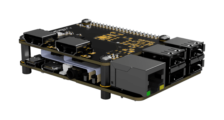
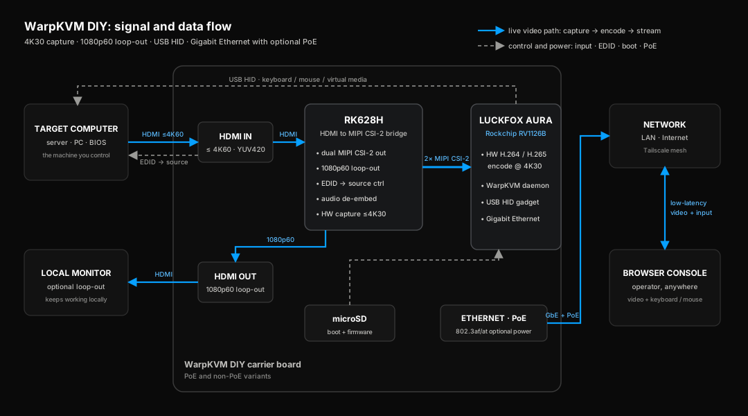
More photography lands here as the first production units come off the bench.
The Luckfox Aura, our variant
The compute board is a Luckfox Aura built around the Rockchip RV1126B: four Cortex-A53 cores, a hardware H.264 / H.265 encoder rated to 4K 30, Wi-Fi 6, Bluetooth 5.4, and Gigabit Ethernet.
Which Aura variant the kit uses
The Aura is sold in several configurations, and the kit ships the 1 GB LPDDR4X build with no eMMC. If you cross-reference the Luckfox wiki, note that its spec table leans on the larger 2 GB and 4 GB builds, some with 64 GB eMMC; the board-level material applies to the kit, but where memory and storage figures differ, the kit is 1 GB, and the only storage is the microSD card.
The board-level facts that matter for a KVM build:
| Item | Detail |
|---|---|
| SoC | Rockchip RV1126B, 4× Cortex-A53 @ up to 1.6 GHz |
| Memory | 1 GB LPDDR4X (kit variant) |
| Storage | microSD only, no eMMC · 8 GB card, about 4.7 GiB free for disk images |
| Encoder | H.264 / H.265, hardware, up to 4K @ 30 |
| Network | Gigabit Ethernet · Wi-Fi 6 · Bluetooth 5.4 |
| USB | 1× USB-C 3.0 OTG · 4× USB-A 2.0 host |
| Camera input | 2× MIPI CSI, 4-lane, 22-pin connectors |
| Buttons | RESET, and BOOT for the Rockchip loader mode |
The kit connects over Ethernet or Wi-Fi, using the included antennas. The USB-A host ports are free for your own use.
The WarpKVM carrier board
The carrier is our own design, in PoE and non-PoE variants, built around the RK628H HDMI-to-MIPI bridge:
- HDMI input, up to 4K @ 60. This is where the target machine plugs in.
- HDMI output for an optional local monitor, at 1080p 60 regardless of what the source sends. The full-resolution path is the network stream.
- Dual MIPI CSI: the carrier routes both of the RK628H's CSI ports to the Aura over two 22-pin FPC cables, one to CSI0 and one to CSI1.
- EDID, presented by the bridge to the source, and rewritable from the console. This is how the kit chooses what the source sends; see Capture modes and EDID.
- On the PoE variant, an 802.3af/at power stage, so one Ethernet cable carries power and network.
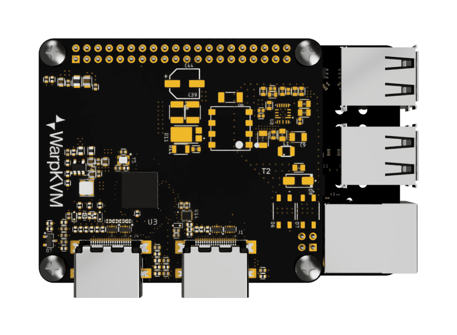
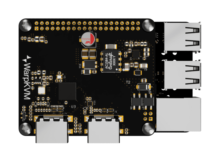
The two variants are the same board; the PoE version populates the transformer and power stage the Standard version leaves empty.
The other supported build: the standalone adapter
The kit carrier is not the only board the image supports. The same RK628H bridge ships as a standalone board, the HDMI to CSI Adapter in its 22-pin version, and a Luckfox Aura paired with that adapter runs the same WarpKVM image. The differences are all subtractions:
- One CSI link, not two. The adapter routes a single 4-lane CSI port, connected to the Aura's CSI0 with one 22-pin cable. The supported modes are the same, up to 4K30.
- HDMI input only. There is no local monitor output on this build.
- No PoE. You power the Aura directly.
The carrier is the build we recommend and the one the kit ships: dual CSI, the local HDMI output, and the PoE option. The adapter path exists for builders who already own the adapter or want the smallest possible build. The adapter's own page carries its measured mode tables and driver notes.
Two USB-C ports, two different jobs
The assembled kit has two USB-C ports, and they are not interchangeable:
- The power port takes 5 V in on the Standard kit. On the PoE variant you can ignore it entirely and power from the network cable.
- The target port is the Aura's USB-C OTG port. It connects to the machine you want to control and carries the emulated keyboard, mouse, and mass storage. It does not power the kit.
Plugging power into the target port is the most likely assembly mistake, and nothing is damaged if you do; the kit simply does not start. Trace the cable before you power on.
The four USB-A ports face the other way: they are host ports, for devices you plug into the kit, and are unused by WarpKVM itself.
Power
The Standard kit powers over USB-C at 5 V or over the 5 V DC input. Use a proper 5 V 3 A supply: a plain adapter such as the official Raspberry Pi one, not a fast-charge or USB-PD charger, not a laptop's USB port, and not a power bank. The PoE variant takes power from any 802.3af or 802.3at switch or injector.
Measured with a meter inline on the supply:
| Condition | Wall power |
|---|---|
| Peak, during boot | 3.7 W |
| Sustained, 1080p 120 capture / 60 encode, client streaming | under 4 W |
| Sustained, 4K30 capture and encode, client streaming | under 4 W |
Boot is the peak, and neither operating point moves it. Against the 12.95 W that 802.3af guarantees, the kit runs with more than a 3× margin, which is why the PoE variant does not need an 802.3at budget.
Thermals
Measured on the bench unit, which wears a small heatsink on the SoC, with no case and no airflow: 47 °C idle, 52 to 54 °C after around 20 minutes of continuous 4K encode, with no throttling and zero thermal events. The SoC does not use frequency scaling at all, so there is no hidden performance cliff; what you measure cold is what you get warm.
The kit does not need a heatsink and ships without one. A vented case is still a good idea, and enclosure guidance will land with the assembly guide.
The CSI cables
The 22-pin FPC cables are the highest-consequence connections in the build: two of them on the kit carrier, one to CSI0 on the standalone adapter build. For each one:
- The kit must be powered off when you seat them.
- At the Aura end, the contacts face toward the Ethernet port.
- Open the latch, seat the cable fully and squarely, close the latch, and check it cannot be pulled out with a gentle tug.
A cable seated backwards or at an angle does no damage, but capture will not start until it is re-seated correctly.
Pin-level references
We do not restate pin numbers we have not verified. For the 40-pin header, the debug UART pins, and the analog inputs, use Luckfox's own material:
- Luckfox Aura pinout, as diagrams.
- luckfox-aura-docs on GitHub, which carries the schematics, CAD, and 3D models. The schematic is the authoritative source for anything the wiki shows only as an image.
- The RK628H datasheet for the bridge itself, with the caveats noted on the adapter page.