
WarpKVM ATX Inline
Remote power and reset over Wi-Fi, inline on the front-panel header. Built for the ASRock pinout.
WarpKVM ATX Inline seats between the case's front-panel connectors and the 9-pin header on the motherboard. The case's own buttons keep working exactly as before, and the card adds a wireless trigger: power tap, reset, and a five-second force-off from the companion app, plus live power and drive-activity telemetry read from the LED lines it sits on. Paired with a WarpKVM DIY Kit, the same controls appear in the kit's console as well; that pairing is part of the kit's launch image.
It runs from the ATX 5 V standby rail, so it stays on your Wi-Fi while the machine is shut down and can bring it back to life.
FCC certification pending
WarpKVM ATX Inline has not yet been authorized under the rules of the FCC. It is currently sold for development and evaluation use while certification is in progress. We'll publish the grant here once it lands.
Compatibility, read this first
The card is a fixed inline board, not a set of flying leads. Its pin routing is built for the ASRock 9-pin System Panel Header (PANEL1) arrangement, which follows the common Intel front-panel layout:
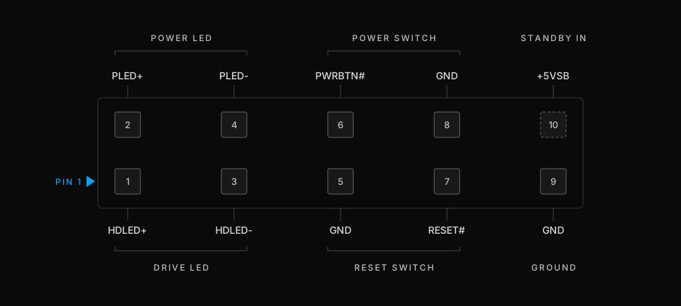
| Pin | Signal | On the card |
|---|---|---|
| 1 | HDLED+ | Drive-activity telemetry, passed through |
| 2 | PLED+ | Power-state telemetry, passed through |
| 3 | HDLED− | Drive-activity telemetry, passed through |
| 4 | PLED− | Power-state telemetry, passed through |
| 5 | GND | Reset return |
| 6 | PWRBTN# | Power pulse, in parallel with the case button |
| 7 | RESET# | Reset pulse, in parallel with the case button |
| 8 | GND | Power-button return |
| 9 | GND | Ground |
| 10 | +5VSB | Standby power in, on the card's input row only · this position is the key on the board header |
Many consumer boards match this layout. Not all do, and OEM machines from Dell, HP, and Lenovo usually do not. Check the System Panel Header diagram in your board's manual against the table above before installing. If a signal sits on a different pin, the card will pulse the wrong line.
If your header differs you have two options:
- Custom pinout. Write to hello@warpkvm.com with your board model or a photo of the manual's header diagram, and we will build the card to match it.
- Jumper wires. Seat the card away from the board and connect each position individually with standard 2.54 mm jumper wires, matching signals rather than positions: card pin 6 to your board's power-switch pin, card pin 7 to reset, and so on from the table above.
What you'll need
- A WarpKVM ATX Inline
- A motherboard with the ASRock 9-pin front-panel pinout, per the section above
- A 2.4 GHz Wi-Fi network. The card does not join 5 GHz networks, so a 5 GHz-only SSID will not appear during setup
- A phone with Bluetooth and the WarpKVM companion app, for the one-time setup
1. Install
Switch the PSU off at the wall before installing. The front-panel header itself is unpowered, but the standby rail around it is live whenever the supply is plugged in.
- Unplug the case's front-panel connectors from the board's 9-pin header. Note where pin 1 is marked on the board's silkscreen.
- Seat the card onto the header, matching its pin-1 marking to the board's.
- Plug the case's front-panel connectors onto the card's passthrough pins, in the same arrangement they came off the board.
- Clip the included T-splice onto the supply's 5 V standby wire. On the 24-pin ATX cable that is the purple wire, pin 9. The splice taps the wire without cutting it. Land its lead on pin 10 of the card's input row, the top-right position that has no pin on the board header.
- Power the supply back on at the wall. The machine does not need to boot; standby power is enough for the card.
Press the case's power button once to confirm the passthrough: the machine should behave exactly as it did before the card went in.
2. Pair
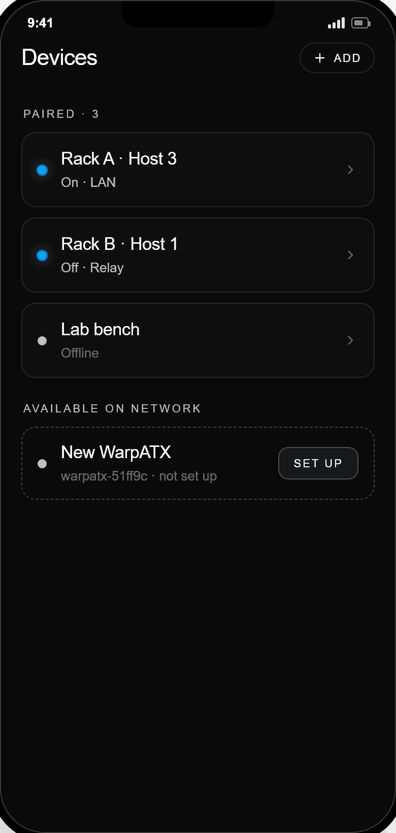
A new card advertises over Bluetooth and the app walks through setup:
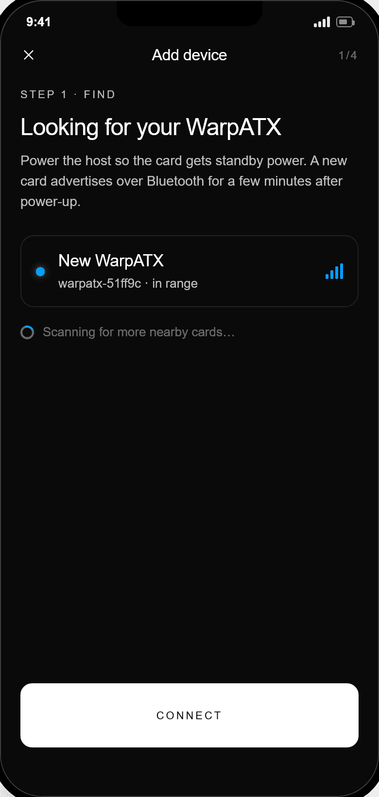
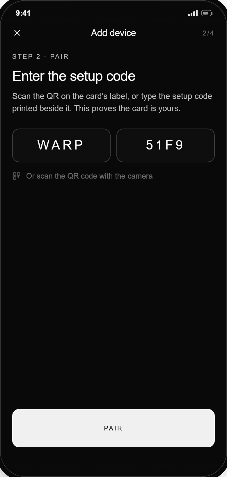
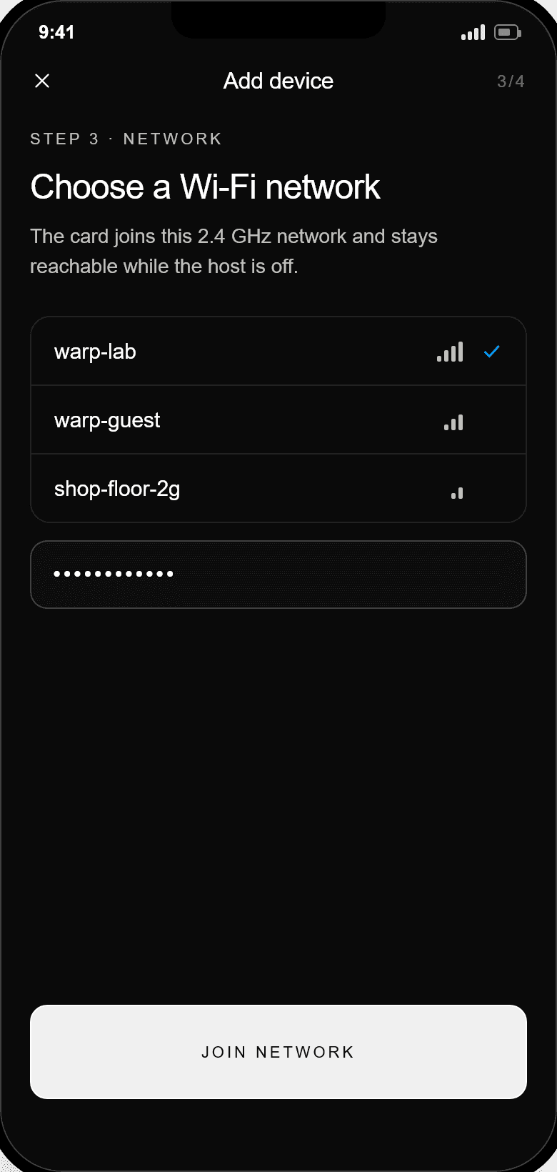
- Add device. The card appears as
WARP-xxxx. Select it. - Enter the setup code printed on the card's label, or scan the QR. Pairing runs over an encrypted session; the code itself is never transmitted.
- Choose a Wi-Fi network and enter the password. It travels from your phone to the card over the encrypted Bluetooth session and nowhere else.
The card joins your network, hands the app its access credential, and registers on the home screen. A mistyped password is not fatal: the card stays in setup and lets you retry.
3. Control
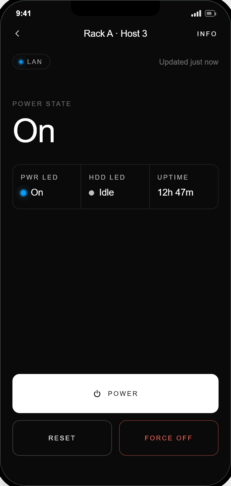
- Power sends a momentary press, 250 ms, the same as tapping the case button.
- Reset presses the reset line, behind a confirmation.
- Force off holds power for five seconds, for a machine the OS has abandoned. Also behind a confirmation.
- Telemetry follows the board's power and drive LEDs, live.
Because the card runs from the standby rail, all of this works with the machine fully shut down. As long as the PSU is switched on, the machine can be started remotely.
Moving it, renaming it, resetting it
From the card's Info screen in the app:
- Rename changes the name shown everywhere.
- Wi-Fi network re-runs provisioning for a new network. The pairing survives; only the network credentials change.
- Factory reset wipes the card's network credentials and pairing so it can be set up from scratch or handed to someone else.
Scripting and integrations
Control does not require the app. On your network the card announces itself over mDNS and serves a local REST and WebSocket API: status, telemetry, and the same power, reset, and force-off verbs, authenticated with a per-device token issued at setup. Write to hello@warpkvm.com for the API reference, or if you want to trigger it from a PiKVM or JetKVM on the same network.
Troubleshooting
The card doesn't appear during setup. It only advertises while unprovisioned. If it was set up before, remove it via the app it was set up on, or factory-reset it from that app's Info screen. Also check that the PSU is switched on at the wall; without standby power the card is off.
My Wi-Fi network isn't in the list. The card is 2.4 GHz only. If your network is dual-band, make sure the 2.4 GHz band is enabled; if the SSID still does not appear, rescan. A hidden SSID can be entered by name during setup.
Setup fails at the Wi-Fi step. Almost always the password. The card returns to setup and lets you retry immediately. Signal strength matters too: inside a steel case, a network at the edge of range may pair but drop later.
The app can't find the card after setup. Discovery uses mDNS on the local network. On iOS, the app needs the Local Network permission; if you declined it, enable it in Settings. The card and phone must be on the same network segment.
Power state reads wrong, or the machine doesn't respond to a trigger. The pinout does not match. Power the machine down, pull the card, and compare your board manual's header diagram against the pin table above. A mismatched header is exactly what the compatibility section is there to catch; get in touch and we will sort out the right pinout.
The case buttons stopped working. The passthrough is passive and does not depend on the card being powered. Check the front-panel connectors are seated on the card's passthrough pins in the same arrangement they came off the board.
Specifications
Control
| Item | Detail |
|---|---|
| Functions | Power tap · 5 s force-off · reset |
| Telemetry | Power LED and drive LED state, live |
| Install | Inline on the front-panel header, no soldering |
| Passthrough | Case buttons keep working, passive, even unpowered |
Compatibility
| Item | Detail |
|---|---|
| Pinout | ASRock 9-pin System Panel Header (PANEL1) |
| Other boards | Custom pinout on request, or re-pin with jumper wires |
| Verify first | Check your board manual against the pin table below |
Connectivity
| Item | Detail |
|---|---|
| Wireless | 2.4 GHz Wi-Fi + Bluetooth LE |
| Setup | Bluetooth pairing via the companion app, per-device setup code |
| Control paths | Companion app · local REST + WebSocket API |
| Discovery | mDNS, announces itself on your network |
Power & build
| Item | Detail |
|---|---|
| Source | ATX 5 V standby rail · T-splice to input pin 10 |
| Host power | Not required, controls a fully powered-down machine |
| Firmware | Open source with signed updates |